|
|
| Modelo: VSC-3M y VSC-6M | Modelo: SEATCUT 20100 y VSC-B |
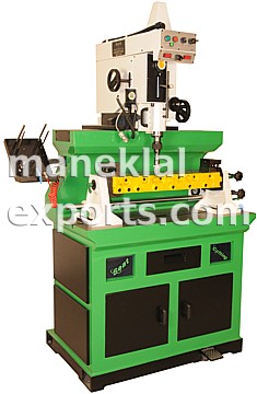
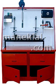
| Modelo: VSC-3M y VSC-6M |
|
 |
 |
| Especificaciones: |
| Modelo: | VSC-3M | VSC-6M |
| Husillo (mm): | 60 | 65 |
| Carrera Máx. del Husillo (mm): | 130 | 150 |
| Inclinación Máx. del Husillo: | 20o | 30o |
| Distancia entre Mesa y Husillo (mm): | 310 | 410 |
| Diámetro Min. de Asiento para Cortar (mm): | 14 | 14 |
| Diámetro Máx. de Asiento para Cortar (mm): | 40 | 60 |
| Velocidades de Husillo (variable): | 25 - 200 rpm | 50 - 300 rpm |
| Carrera del Porta-husillo (frente y detrás) (mm): | 40 | 60 |
| Carrera del Porta-husillo (izquierda y derecha) (mm): | 700 | 850 |
| Carrera de Bloque de Fijación (frente y detrás) (mm): | 130 | 150 |
| Tamańo de la Mesa de Fijación (mm): | 500 x 1000 | 600 x 1100 |
| Motor del Husillo: | 1 HP | 1 HP |
| Requerimiento de Aire Comprimido: | 100 psi 4 bar | 100 psi 6 bar |
| Peso Neto / Bruto (kilo): | 650 / 1050 | 700 / 1100 |
| Dimensiones (m): | 1.25 x 1.00 x 2.20 | 1.45 x 1.15 x 2.35 |
| Volumen del Embarque (m3): | 3.0 | 4.0 |
|
Accesorios Estándar: Con VSC-3M: Juego de Pistola de Aire Comprimido, Sistema de Centrar Digital, Placa para Fijación de Cilindro Sencillo, 5 pzs. Guías del Vástago en Acero, 2 pzs. Herramienta de Corte (45o), Rotula (porta-herramienta) de 0.236” / 6 mm, Porta Herramienta de Corte (14 a 25 mm), 6 pzs. Resortes en Acero Inoxidable, 4 pzs. Casquillo de Latón, Mecanismo para Inclinar y Levantar Culatas, 2 pzs. Placas para Soportar Culata, juego de Llaves, 4 pzs. Pernos para Nivelar Con VSC-6M: Juego de Pistola de Aire Comprimido, Sistema de Centrar Digital, 10 nos. Guías del Vástago en Acero, 2 pza. Herramienta de Corte (45o), 1 pza. Herramienta de Corte (30o), 1 no. Herramienta para Biselar (45o), 1 no. Herramienta de Fase (Phasing Tool) (90o), Rotula (porta-herramienta) de 0.236” / 6 mm, Rotula (porta-herramienta) de 0.375” / 9.5 mm, Porta Herramienta de Corte (14 a 25 mm), Porta Herramienta de Corte (24 a 40 mm), Porta Herramienta de Corte (40 a 60 mm), 6 pzs. Resortes en Acero Inoxidable, 6 pzs. Casquillo de Latón, Mecanismo para Inclinar y Levantar Culatas, 2 pzs. Placas para Soportar Culata, juego de Llaves, 4 pzs. Pernos para Nivelar Accesorios Opcionales: Juego de Probador de Vacío, Dispositivo de Medición de Profundidad, Rectificadora de Herramientas de Corte, Unidad para Pulido, Porta Herramientas Adicionales en distintos tamańos, Insertos, Escariadores, Taladros, Guías del Vástago en Acero o Carburo, Pilotas, etc. |
|
|
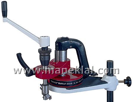
| Modelo: Seatcut-20100 y VSC-B |
|
 Modelo: Seatcut-20100 |
Presentaciones: |
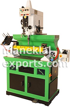
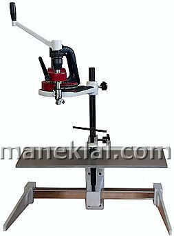
 Modelo: VSC-B |
Especificaciones:
|
|
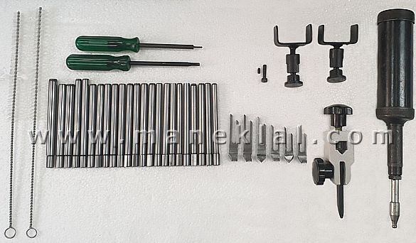 |
Accesorios Estándar: Máquina básica, Herramientas, Caja, Formtools y Pilotas (detalladas abajo), Base para montar sobre pared con tornillos de montaje especiales (apropiado para montar todos tipos de culatas). (Para el modelo VSC-B, en lugar del base para montar sobre un pared, un banco y accionamiento por motor suministrado, como mostrado en la foto arriba) Formtools, Pequeńos (diámetro 24 a 34 mm): 1 pieza 15o x 45o x 75o - 1.5 mm ancho de asiento, 1 pieza 0o x 30o x 60o - 1.5 mm ancho de asiento, 1 pieza contra-mecha Formtools, Grandes (diámetro 34 a 44 mm): 1 pieza 15o x 45o x 75o - 1.5 mm ancho de asiento, 1 pieza 0o x 30o x 60o - 1.5 mm ancho de asiento, 1 pieza contra-mecha Pilotas (23 piezas): 6.980, 6.995, 7.930, 7.952, 7.980, 7.995, 8.002, 8.020, 8.500, 8.520, 8.641, 8.672, 8.685, 8.692, 8.705, 8.709, 8.718, 8.725, 8.980, 9.000, 9.980, 11.086 y 11.105 mm
|
 Base para Montar sobre Pared |
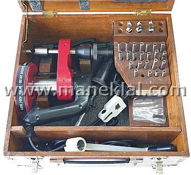 Seatcut-20100 en Caja de Madera |
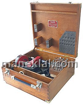 Seatcut-20100 en Caja de Madera |
|
|
|
|
|
Operation Sequence for Valve Seat Cutting Machines |
 Fastening of the Pilot Select a Pilot that fits snugly into the valve guide. Tighten the grub screw to hold the pilot in place. (Please note that a snug fit is essential for a perfect finish on the valve seat) |
 Mounting of the Formtool Select the Formtool as per the engine manufacturer’s specifications and insert it into the tool slot
|
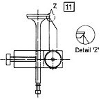
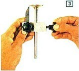 Gauging for Valve Connect Area Insert the valve stem into the formtool setting gauge as shown and slightly tighten the lock screw, permitting the gauge to be movable. Bring the tip of the pointer into contact with the valve face and lock it at the outer diameter of the desired future seating area (Refer fig. 11 below) |
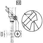
 Transferring the Valve Diameter to the Formtool Insert Formtool setting gauge over the pilot and tighten it so that it is still movable. Loosen the Formtool lock screw and let the Formtool tough the tip of the gauge pointer just at the meeting point between the seat angle and the external correction angle. This meeting point would be the outer diameter of the desired future seating area (Refer fig. 12 below) |
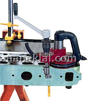
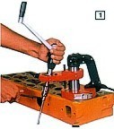
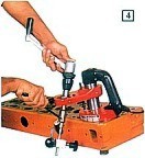
 Positioning the Unit The Pilot is now introduced into the clean guide. Hold and guide the unit with both hands as shown in the figure. Place the magnetic base on the cylinder head / steel plate, suitably maneuvering it. Adjust the pre-setting screw so that the tool does not tough the seat. Centre the unit by turning the drive handle 2 or 3 turns. |
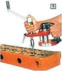
 Locking After centering, energize the electromagnet by putting the switch to position 1 and lock the swiveling arm. Repeat this 2 to 3 times to ensure proper alignment. A uniform load will be felt on the handle if the centering is correct.
|
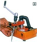
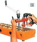
 Seat Cutting Operation Having set the machine, turn the drive handle clockwise as regularly as possible, operating the advancing device as required. (Never turn the handle in the anti-clockwise direction when the Formtool is under pressure as this would damage the carbide tip) In case of very tough chromium seats, rub the seats with an abrasive cloth and use a suitable lubricant - gasoline or kerosene - during cutting operation |
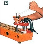
Removal of the Unit When the seat is ready, retract the tool by a few turns of the advancing device. Demagnetize the base by pressing the switch to position 2 for a moment. The unit may now be transferred to a similar seat without any further adjustment. Note: Only one tool setting is necessary per seat diameter Lubrication: If the unit is in continuous service, it may be oiled daily at the 2 oil nipples located in the swiveling arm and the knurled nut. |
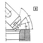 Tool Geometry |
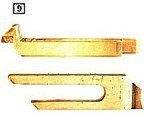 Formtools |
 Formtool Setting Gauge |
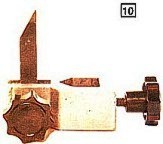
 Seat Gauging |
 Dimension Transfer |
|
|
Maneklal Global Exports |
|
A NUESTRA PÁGINA DE MAQUINARIA PARA RECONSTRUCCIÓN DE MOTORES |
|